
Two components make up this portion of the vehicle's electrical system; the key cylinder and the switch itself. Both parts are available at NAPA stores if you can't find them elsewhere. Removal of the assembly consists of two simple steps. First, carefully remove the modular plastic plug from the back of the switch (performed behind the dash). Next, spin the chrome ring around the outside of the key cylinder in a counter-clockwise direction. You may need pliers to loosen the ring; if so, cover the jaws with a layer of thick tape to avoid marring the ring (Dodge dealers probably had/have a special tool for these but this procedure works fine). Drop the switch assembly out from the dash and grab your keys--you'll need them to release the cylinder from the switch. Once ready to separate the switch from the keyed cylinder, simply insert your ignition key and turn it as if you were to turn the truck on. Now, pull the larger switch body away from your key and the two should release.
You'll also need your key (new or old) to put the switch body and key cylinder back together. Insert your ignition key into the cylinder and turn it; you'll notice that a spring loaded detent will lower itself allowing you to place the cylinder back into the switch body. Place the assembly back in its proper hole in the dash, then screw the chrome ring back onto the end of the protruding switch. When the assembly is secure, re-attach the modular electrical plug at the back of the switch.
After tracing all the wires from the turn signal switch to the back of the truck (using nothing more than a test light), I realized that current was flowing but the lights still weren't getting the juice. Even though I sanded around the screw holes and flanges of the light housing with sandpaper, a good ground was not present at either side of the truck. To fix the problem, I prepared two wires that were long enough to reach from the metal light housing down to the frame. Onto each end of both wires I crimped a soliderless connector that would accept a pop rivet. Holes were drilled on both the light housing and the truck's frame and pop rivets were fastened through the connector ends of the wires to hold them onto the frame and each housing.
Generally speaking, since the truck bed is just a big hunk of metal the procedure of sanding the contact points of the bed and housings should have worked. In my case, the bed (for some reason) does not have good metal to metal contact with the frame. Wood blocks were used as spacers to mount the bed onto my truck but metal bolts fasten the bed to the frame. Strange? Who cares, they work now!
Grounds are required for direct current devices (i.e. automobiles) because the flow of electrons must have a return path to the source (battery). Without the return path, the electrical pressure (voltage) cannot overcome the resistance to electron flow and thus nothing happens with the non-grounded device.
First things first. DON'T THROW OUT YOUR OLD SWITCH! You may need it to adapt the new switch to your truck. This may not be true for all truck years or models, but on my truck the little switch has a threaded portion which allows it to be fastened through a hole with a thin sheetmetal "quick nut". The new NAPA part I got was nearly identical to the old version but it did not have the threaded part. Instead, it had a metal clip which may be used for attachment on other Dodge Truck models (if you can clear this up, let me know). If you find yourself in the same situation, don't worry. Here's how you you remedy the situation using the old part and the almost correct NAPA part. Now, prepare to destroy the old switch (it took some guts on my part because I wasn't sure that I could do this and a replacement part would be days or weeks away). This is necessary because you need the threaded portion to be added to the new part (kinda like other stuff on these trucks, just replace the bad components and reuse the good). What I did to accomplish this is not really scientific, just break all the plastic and innards of the old switch that you can until the center is clear for a big drill bit. Once nearly everything has been busted off but the threads and some plastic, use a drill and the large bit to carefully drill out the rest of the plastic. DO THIS WITH CAUTION - hurried drilling can destroy the threaded metal piece. You may want to hold the busted apparatus with a pair of good pliers that have thick tape applied to the jaws. Do this by holding the part by the threads with the protected jaws of your pliers. If you did this right, all the plastic should have been removed by the drill bit and all that is left is the threaded metal ring.
The new NAPA part will gladly accept the threaded ring in the same position as the old switch. On mine, the ring went on too far (I think the new switch is a little shorter than the old) and required that the switch be adjusted all the way forward. Even at this position the switch doesn't always get pushed by the pedal and my brake lights occasionally stay on. I haven't done this, but try using some hot glue or super glue gel to make the threads fit a little ways back on the switch if you have the same problem.

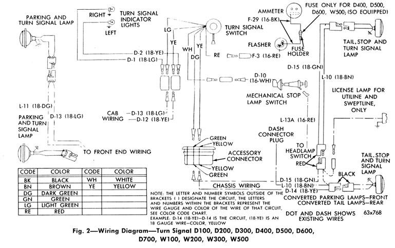
I can't remember what the name of the company that reproduces the turn signal cams is but I can tell you that one part number is S-9 and the other is S-12. The fundamental difference between the switches is that the switch with the horn ring just has a simple plastic part that cancels the turn signal. For those of us with the more common horn button steering wheel, we have more work to do to replace ours. The switch for the more common horn button wheel/column has integrated wires and connectors which allow the signal to operate and cancel with one part. To change either part one must first remove the press fit washer from the cam and then worry about the other stuff. Just swap the cam if you have the simpler setup. Solidering and splicing is required for the rest of us. Nonetheless, the time spent is well worth it considering that you won't have to cancel your turn signals anymore!